- 10 月 17, 2020
- News
- 0 Comments
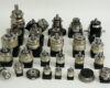
The main function of the reducer is to change the speed and torque between the primary motivation and the actator, and is widely used in the machinery and metallurgical industries.
There are many types of gear reducer transmission devices, mainly cylindrical gear reducers, conical-cylindrical gear reducers, planetary gear reducers, gear-worm reducers, special gear reducers, etc.
This paper shares the main types of gear reducer transmission, different installation methods, lubrication and sealing methods.
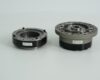
1 The main type of gear reducer.
1.1 Cylindrical gear reducer.
The cylindrical gear reducer is mainly divided into the gradually open-line cylindrical gear reducer and the arc cylindrical gear reducer. Among them, the gradually open line cylindrical gear is widely used, but also can be divided into straight teeth, oblique teeth and human teeth.
The re-effect of oblique teeth is greater than that of straight teeth, and the noise and wear are small, which is generally used for the transmission of heavy-duty machinery. The choice of reducer should be based on the circular speed, load conditions and working conditions and other practical factors to choose.
At present, the gradually open line cylindrical gear reducer has the advantages of easy processing, easy manufacture, easy assembly, high precision, center distance change does not affect its normal meshing and so on.
Because of its large carrying capacity range, the range of public input power and public output torque is large, and it is widely used in metallurgy, mining, transportation and other equipment in China. Since the teeth are wire contact, this type of reducer requires higher precision and stiffness of the parts of the gear mechanism.
1.2 Cone – cylindrical gear reducer.
Conical-cylindrical gear reducer is a transmission device for vertical arrangement of the input and output axes. The first stage of this type of gear reducer is the Gleason arc tooth cone gear, which can also be used with other profiles, and the first and third stage drives are gradually open-line cylindrical oblique gears.
The gears and bearings of these reducers are generally splash lubricated and cooled naturally. Such reducers have the advantages of high carrying capacity, low noise, small size, light weight, high efficiency and long service life, and are widely used in metallurgy, coal, transportation, building materials and other machinery and equipment.
1.3 Planetary gear reducer.
There are many types of planetary gear reducers, including universal planetary gear reducers, various small tooth differential reducers, harmonic gear reducers and three-ring reducers.
The advantage of this type of reducer is that it can be made into a single-stage, two-stage and multi-stage reducer, so the transmission ratio range is large, and has the characteristics of compact structure, light weight, large carrying capacity, small profile size and so on. However, its structure is complex, manufacturing accuracy requirements are high, assembly and maintenance is more difficult, the price is high.
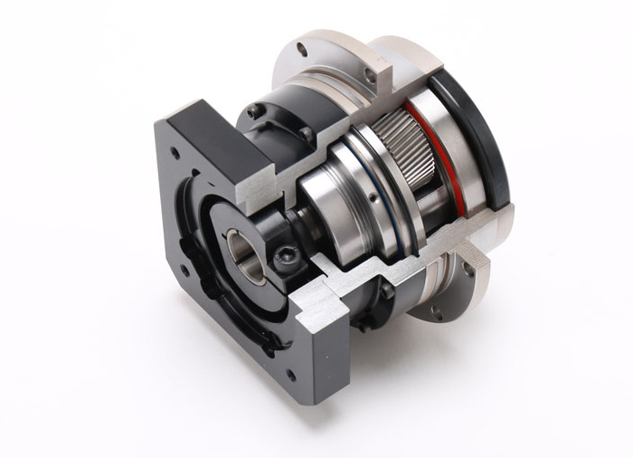
2 Gear reducer installation, lubrication, sealing.
2.1 How to install the gear reducer.
1) Solid shaft fixed installation.
This installation method is to connect the output shaft of the gear reducer with metallurgical machinery through couplings, scabies, gears, wheels, etc., and the gear reducer is securely mounted on a solid, vibration-free basis. Currently, most gear reducers can be installed in this way.
For large gear reducers, threaded holes should also be machined on the feet of the body in order to adjust the mounting position by adjusting the position with adjustment bolts, and for gear reducers in the amplitude mechanism, pin latches should also be used to lock to prevent movement during installation.
2) Hollow shaft single-point floating installation.
This installation is done by using the output shaft of the gear reducer as a hollow shaft, which is connected to the working mechanical drive shaft by a swelling sleeve, while the entire drive device, including the motor, coupling, brakes, retarders, etc., is mounted on the support of the drive, and then supported by a ball ream or bearing.
The installation principle is that the ball reaming support point and the center of gravity of the transmission device deviate from a distance, in the working state, the bending moment caused by the eccentricity of the support point can be balanced with the bending moment caused by the load of the drive device, so the theoretical upload shaft is not subject to additional force.
3) Hollow shaft suspension installation.
This installation is done by connecting the output shaft of the decelerator with the metallurgical mechanical shaft using a expansion sleeve, supported by the output shaft and another torque rod. This installation method is simple, saves floor space, and reduces the weight of the whole machine, and is suitable for transmission devices that transmit power from the vertical direction.
2.2 Lubrication method for gear reducers.
The effect of lubrication has a great effect on the gear reducer. If the lubrication conditions are not good, the heat generated by the gear reducer increases and its carrying capacity decreases. Therefore, the oil and oil quantity must be selected correctly in order to effectively ensure the normal operation of the gear reducer drive and extend its service life.
Typically, the lubrication method is lubricated by the oil pool and cooled naturally, while when the high-power gear reducer or thermal power is not enough, it can be cooled by pressure cycle oil lubrication or with a cooling device.
Under normal operating conditions, when the ambient temperature is (0 to 35) degrees C, or when using circulating oil lubrication, it is recommended to choose medium-load industrial gear oil 220, when the ambient temperature is (35 to 50) degrees C, the selection of medium-load industrial gear oil 320. In addition, the retarder should be replaced after the initial operation of 400h.
2.3 The sealing method of the gear reducer.
1) Skeleton oil seal.
Most gear reducer shaft seals, are generally used elastic lip seal, this sealing method has the characteristics of easy installation, good use, and standard parts supply. When the oil seals are used in pairs, grease should be filled with empty questions between the two seals.
When sealed in this way, the shaft neck surface with the seal should be hardened or chrome plated to ensure that its hardness is ≥ 30HRC. At the same time, in order to ensure that its surface roughness is controlled in Ra (0.25 to 0.63) m, cutting method can also be used for grinding during machining.
2) Combined seal.
The combined sealing method uses a triple sealing structure, which does not affect the lubrication of parts but also effectively prevents leakage. The first seal is on the outside of the filling hole, at the same time in the oil bezel side of the appropriate position (to ensure that the bearing lubrication necessary oil level), drilling through the inside of the tank oil return hole, basically to ensure the smooth flow of large-flow lubricant return oil.
In addition, between the first seal and the second seal, directly below the hole in the box body, there is also a second return hole drilled to ensure that the oil squeezed out of the small pores has a channel back to the box.
The second seal is a set of thin steel plates consisting of 3 to 5 sheets and a thickness of 1.0 to 1.2 mm. At the end of the seal and the lower part of the end cover, drill another return oil hole to ensure that the last remaining oil flows back into the tank.
The third seal is a filler seal, using a new filler, carbon fiber, which is pressed between the shaft and the end cap. This sealing material self-lubrication is very good, and heat- and corrosion-resistant, long service life, can play a good role in the gear reducer oil- and dust-proof.